Click on each image to see a larger image
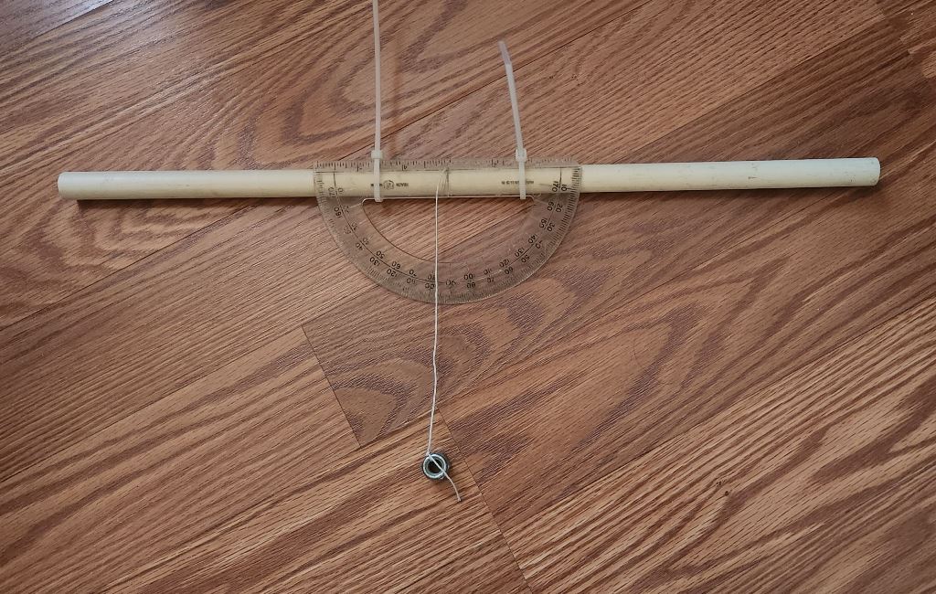
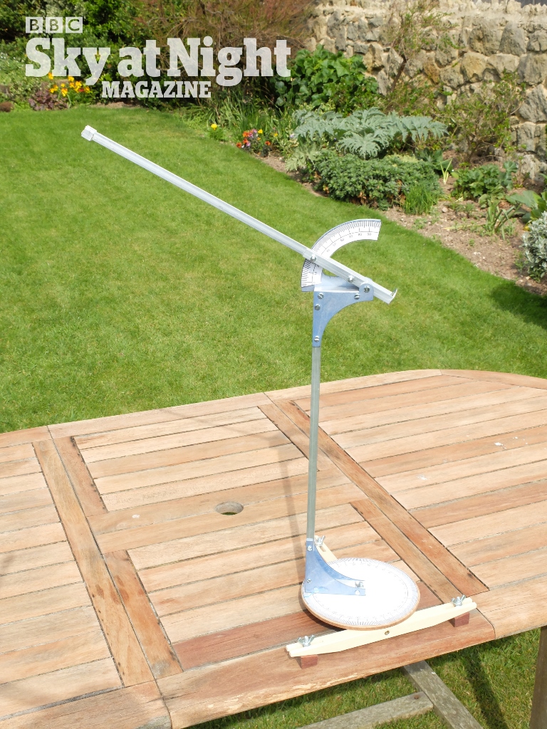
In the beginning, I made this hand held transit quadrant. Although it was functional, it did not have the accuracy that I needed for this Activity. Nor was it able to measure any azimuth angle. So I scrapped this idea and used the following Quadrant I found online as a model for what I needed to build.
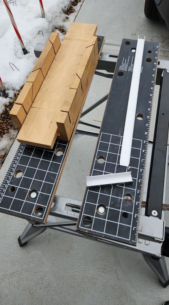
I bought the aluminum to build this quadrant. After making my hand held quadrant in the first picture, my thoughts changed to a hybrid, combining the simplicity of both designs as seen in the above two pictures.
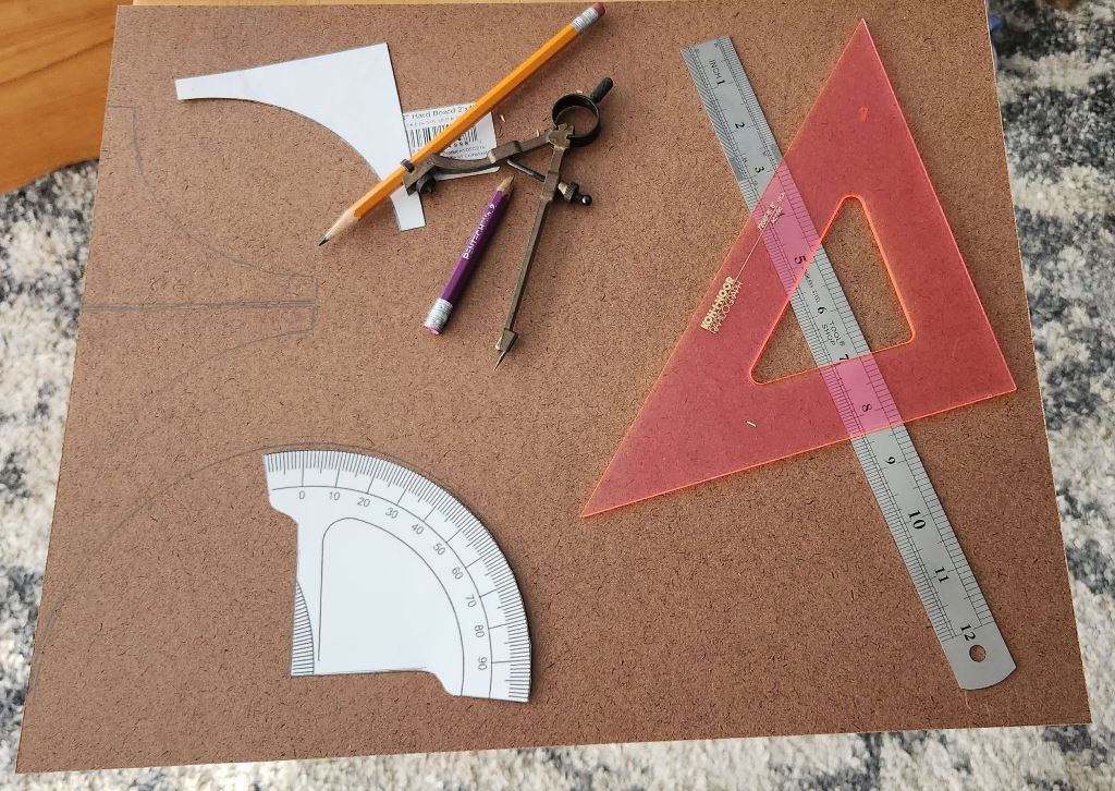
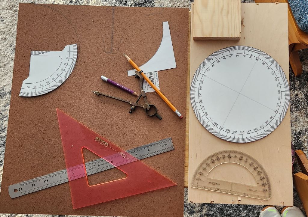
I printed the right angle templates to support the two aluminum pieces. The templates are found in this PDF File.
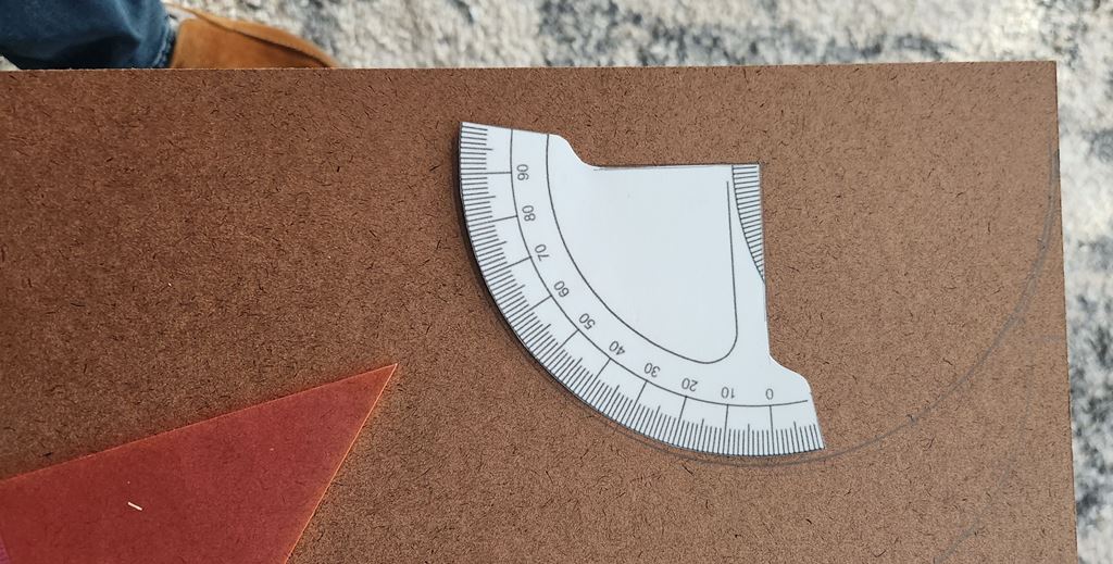
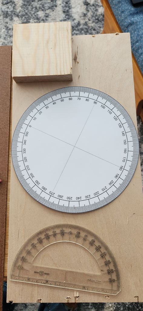
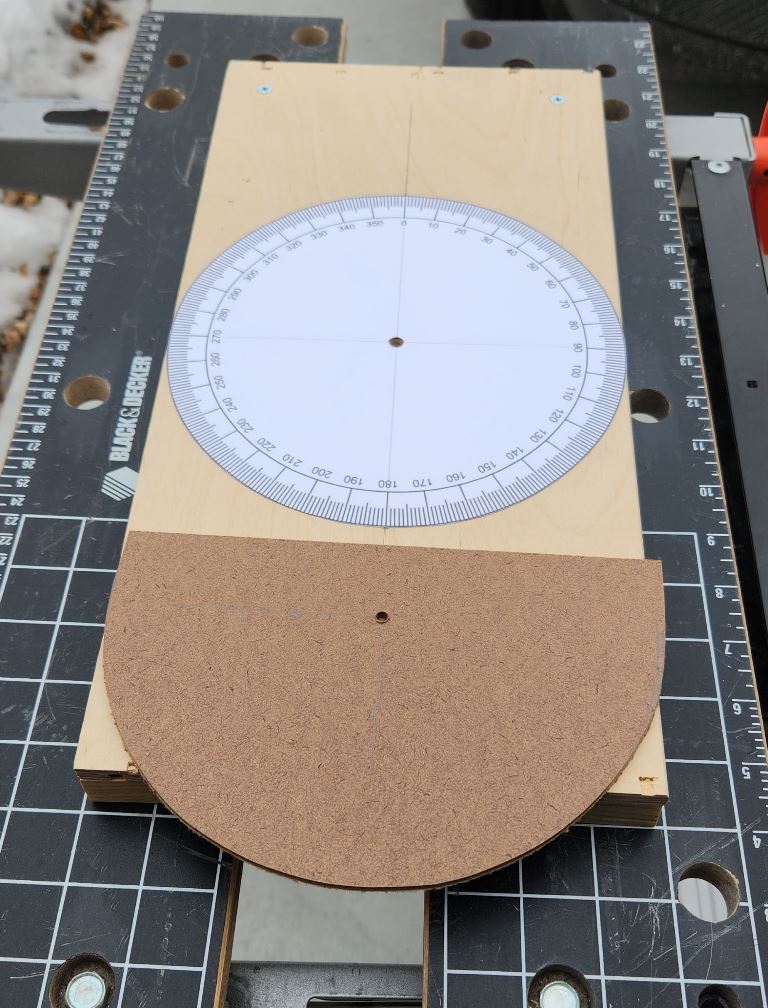
I printed the scales from the second image quadrant, that were included in the instructions. I printed them to a scale where the azimuth scale was about 8 inches in diameter. The altitude scale had a radius of about 4 inches. These templates can be found in this PDF File.
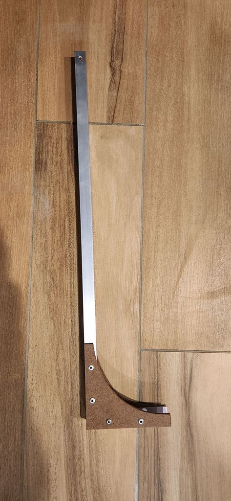
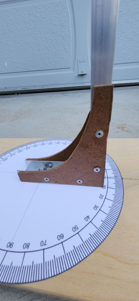
The radius of the altitude plate and scale is 4 inches from where the pivot point will be. The length from the horizontal top, where the sight tube will be, and the bottom of the curve where the 0 degree marker points, is 5 inches. Using a protractor, I carefully aligned the altitude scale to 0 degrees would be horizontal and 90 degrees would be vertical. Where the 0 degrees is, draw a line vertical towards the top and where the 90 degrees is, draw a line horizontal to the right. where these two lines intersect is where the 1/8-inch pivot hole is drilled.
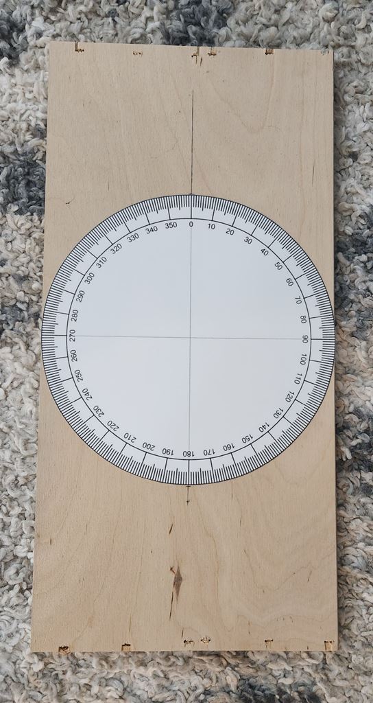
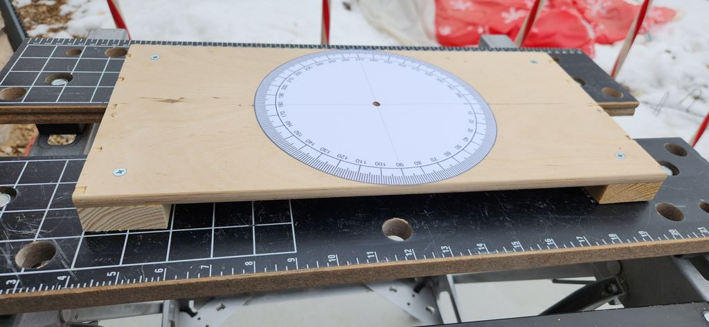
The base measures 16 inches long and 8 inches wide. The board I used was 3/8-inch thick.
I added four 3/4-inch thick and 1 3/4 inches square feet to the bottom side of the base. This would allow me to use angled wooden door shims to fine level the base.
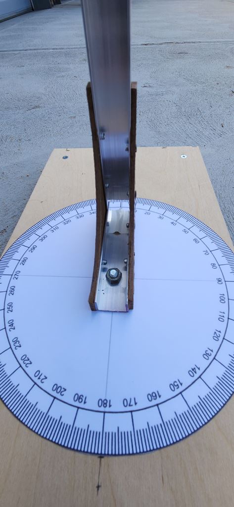
The azimuth scale is 8 inches in diameter. The altitude scale has a radius of 4 inches.
I used 1/8 inch thick masonite board for the altitude plate and the right angle supports (their outline is seen at the top of the masonite piece).
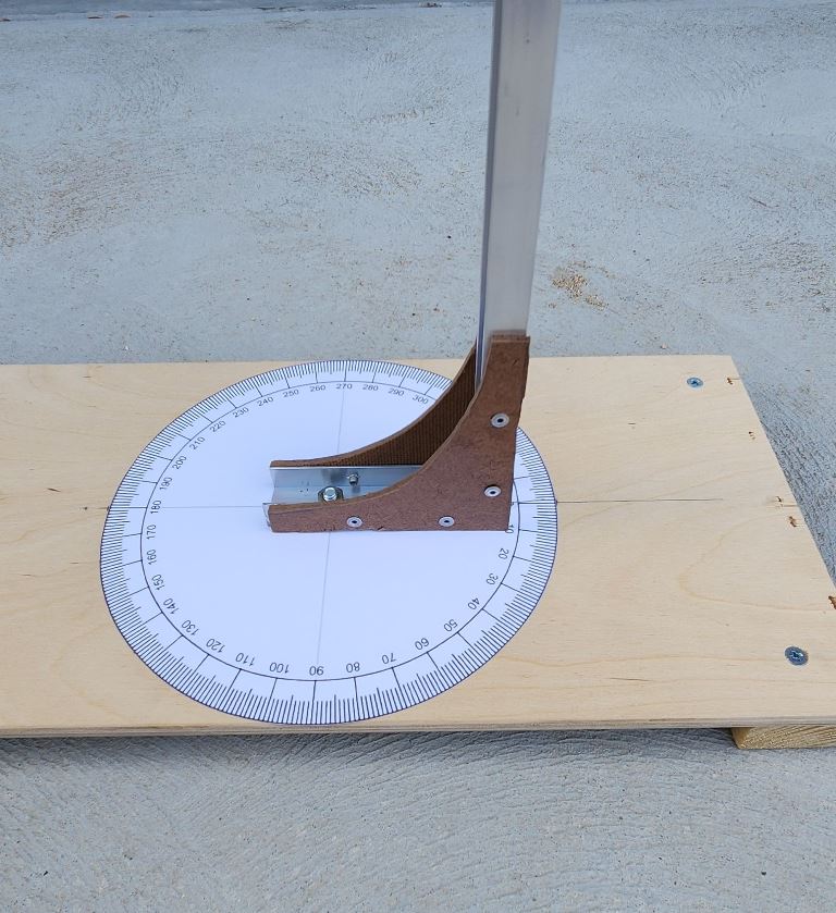
I used contact cement to glue the scales to the azimuth base. The extended line is the north-south line on the board and needs to be aligned on the celestial north pole. From Activity 1, this is a 14 degree offset to the west from magnetic north. This will help me align the quadrant in the field when Polaris is not visible. When Polaris is visible, I aligned the Quadrant's 0 degrees azimuth mark on that star.
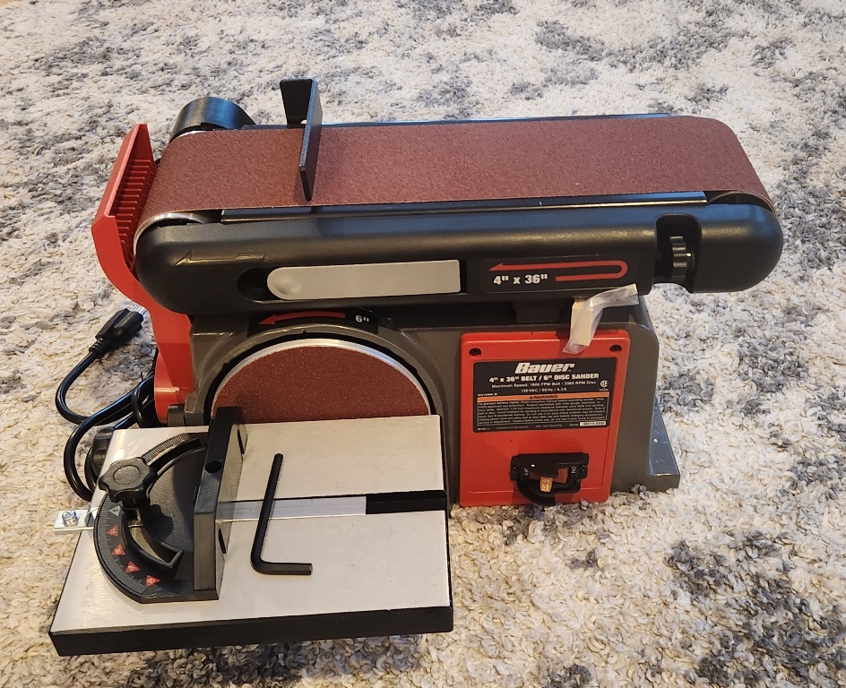
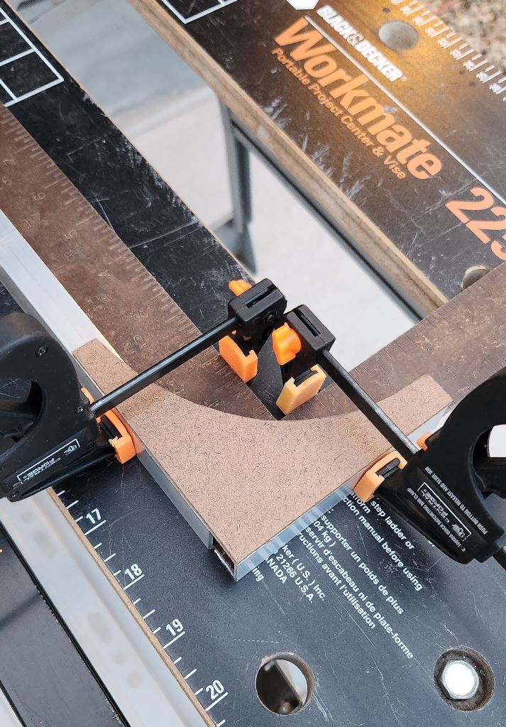
I purchased a new tool to square up the right angle supports. I've always wanted this tool for other woodworking projects. So I bought it now for this project.
I used my hand mitre box and a hacksaw to cut the two aluminum pieces to support the altitude plate. The shorter piece is 4 inches line and the longer piece is 8 inches long. The measurements for the original quadrant can be found in this PDF File. These dimensions are in millimeters.
The hole in the base is a 1/4-inch hole, centred at the intersection of the North-South and East-West directions intersect in the middle.. The hole in altitude bearing is 1/8-inch in diameter.
It was warm here in Colorado on Sunday January 21, 2024. A balmy 53 degrees. I went out in thee driveway and fabricated all the parts I needed.
I added 4 feet to the azimuth base. I will use wedged wooden door shims to level this base before use.
To ensure the base and upright aluminum pieces were at right angles, I clamped them to a large square. I then drilled holes and used 1/8 inch pop rivets to secure the right angle braces to the aliminum pieces.
This is how the vertical shaft turned out. The hole at the top is a 1/8-inch diameter hole to secure the altitude plate to the base.
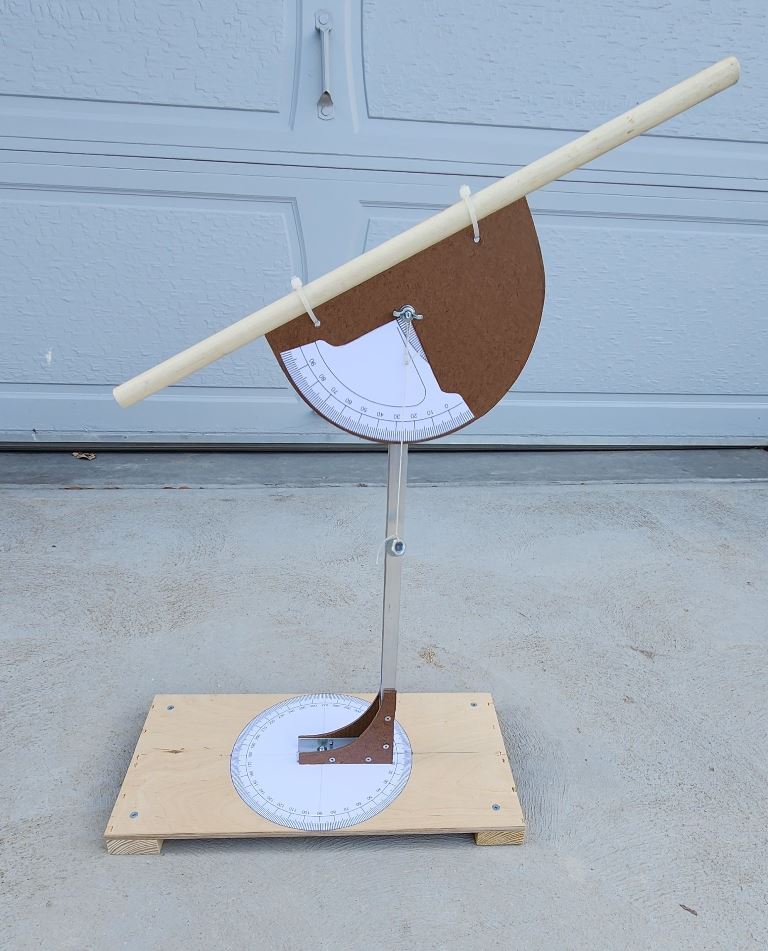
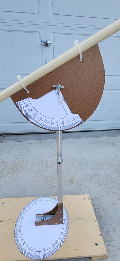
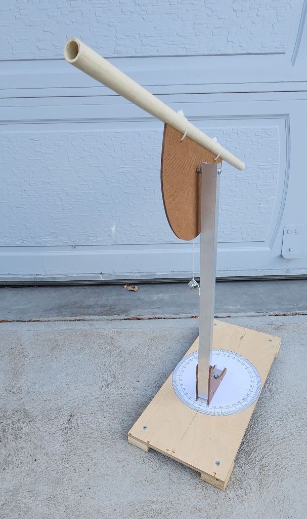
This is the finished quadrant. I used zip ties to secure the spotting tube to the top of the azimuth plate. The tube is 18 inches long.
I used the contact cement to glue the altitude scale to the plate. I took great care to ensure it is at right angles to the site tube.
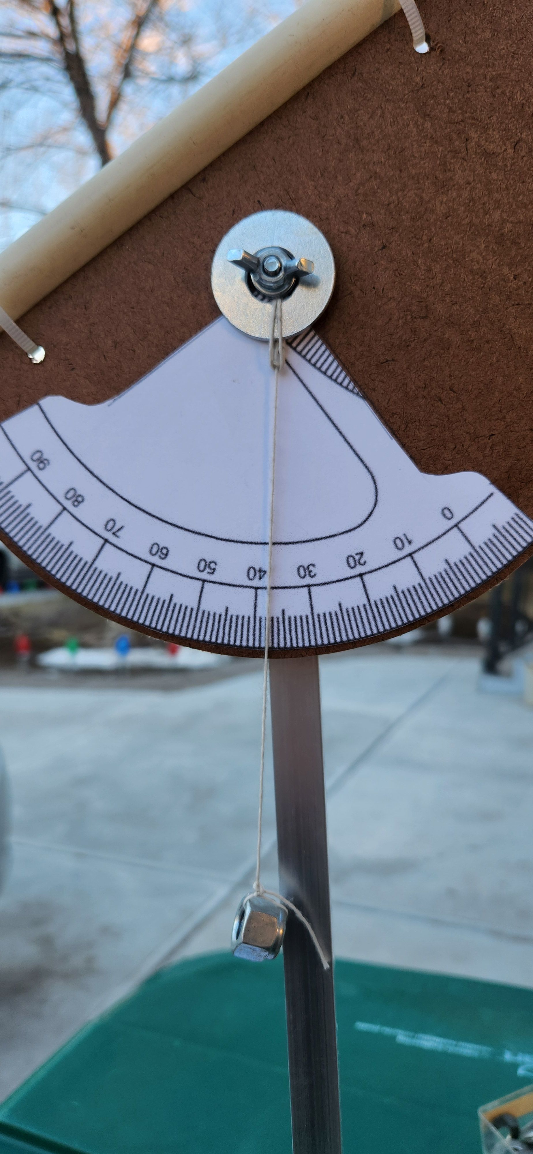
I used kite string to make a plumb bob with a heavy, 3/8-inch nut as the weight.
The azimuth scale.
You can see the 1/4 inch bolt that pivots the azimuth of the quadrant.
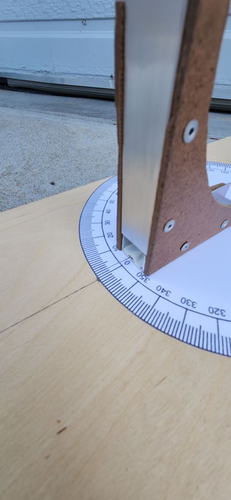
I secured a thin wire to the front of the aluminum to help read the azimuth angle. I taped this wire to the base of the 4 inch piece.
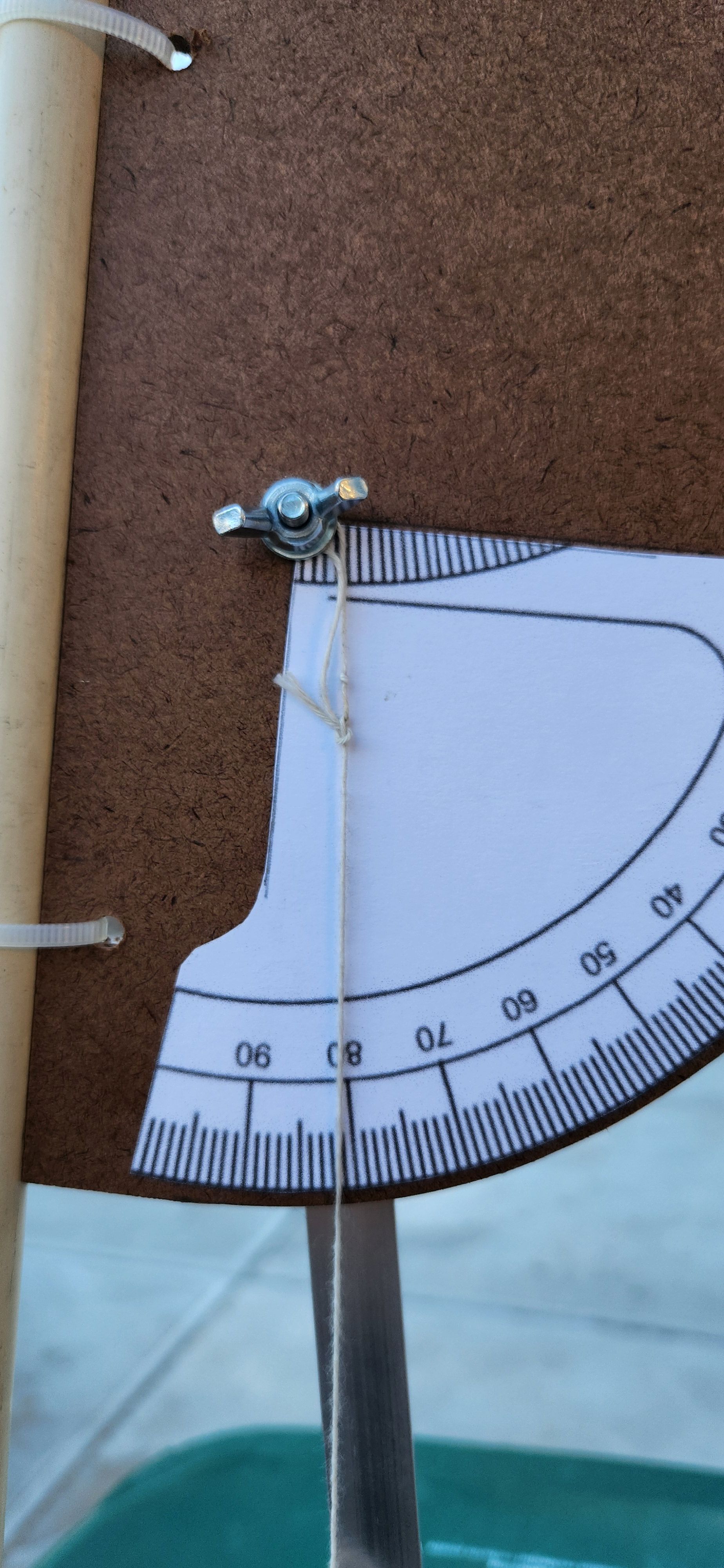
The backside of the altitude plate. The 1/8-inch bolt holding the altitude plate is 2 inches long. I added three nuts between the aluminum piece and the altitude plate to make it stand off the upright aluminum piece better. This helps the plumb bob nut dangle free from hitting the upright aluminum piece.
I used the quadrant for the first time on January 28, 2024. I measured the altitude of Polaris and got a reading of 38.5 degrees. It should have been 39.9 degrees.
What I noticed is that I needed the wingnut tightened enough to help hold the altitude plate in a position without it rotating when I let it go. This pinched the plumb bob string that contributed to the erronous reading in altitide.
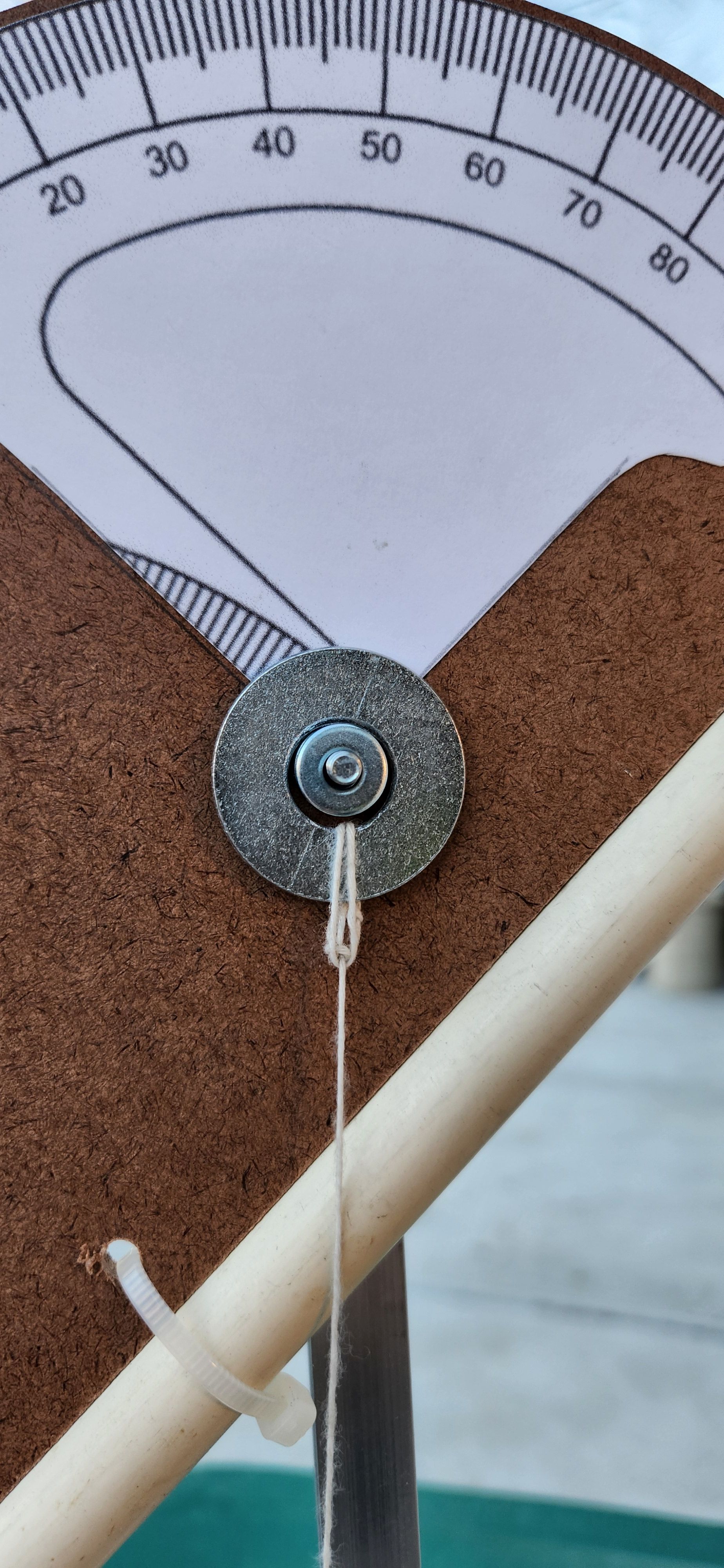
I looked through all my part drawers and found a larger washer I could tie the plumb bob string too and it would rotate freely around three smaller washers inside this larger washer.
Now when you tightened the wingnut, it titghtened on these three smaller washers to add friction to the altitude plate. The plumbbob measuring string now was able to rotate freely and hang vertically down below the pivot point.
I tried this out on January 30, 2024 and the altitude of Polaris now measured just short of the 40 degree mark on the scale. This was a great addition to my quadrant and added the precision I wanted in this instrument.